Yes chromatic aberration is a frequently encountered problem with the Optosplit, but actually the cause is in the microscope, specifically the objective!
It’s all to do with “longitudinal magnification”, which is a potential problem with any high-magnification system such as a microscope. Longitudinal magnification is the SQUARE of the lateral magnification, and this has potentially nasty consequences!!!
Consider for example a x40 objective looking at a one micron cube. What is the shape of the image? Clearly its lateral size is 40 times bigger, ie 40 by 40 microns. But to the extent to which the depth of field allows the image to be in focus more or less through its entire depth, then the size of the image in z is not 40 but 1600 microns! In 3D we thus have a very elongated block instead of a cube.
So how does that relate to the chromatic aberration of the objective? Well, the chromatic aberration means that the focal length changes a bit across the wavelength range. The focal length of the objective is given by the focal length of the tube lens divided by the magnification of the objective (of course!), and a change in focal length is basically equivalent to moving the object by the same amount. But because of the enormous longitudinal magnification, the effect on the image is correspondingly greater. In other words, any chromatic aberration in the objective is ENORMOUSLY magnified.
For a 1:1 relay like the Optosplit, this effect just doesn’t happen, and for the lenses we use the chromatic aberration should be down at the diffraction limit anyway. However, once you split an image between two wavelength ranges, the objective’s chromatic aberration hits you right in the face. Especially true as you go out towards the red, where cameras see images far better than we do, and the objective’s chromatic performance tends to be getting worse in any case!
So, our corrector lenses act like “spectacle lenses”, to compensate for a problem elsewhere. They therefore need to be selected by straightforward trial and error!
And as for flatness of field, EXACTLY the same argument applies. A tiny error in the objective across the field is enormously magnified, and in practice will swamp any such errors in the relay.
So finally, this isn’t a specific problem with anyones objectives! Everyone’s do it to some extent. Customers who do accurate spectral scans have to use something like a PIFOC focusser to move the objective during the scan to compenaste for all this!
There are several ways to achieve bypass with the OptoSplit II:
(1) Remove the dichroic cube, centre the image with the split control, open the aperture and adjust the trim control on the bottom to remove any vignetting.
(2) Leave the dichroic cube in place, block the long wavelength path with the shutter plate provided, centre the image with the split control, open the aperture and adjust the trim control on the bottom to remove any vignetting.
(3) Leave the dichroic cube in place, block the short wavelength path with the shutter plate provided, centre the image with the split control, open the aperture and adjust the trim control on the bottom to remove any vignetting.
This allows non-split mode using either filter in the Optosplit cube, or with neither in place. With a little practice this bypass will only take a few seconds.
For smaller sensors it may not be necessary to adjust the Trim control routinely, but we would suggest observing the effects of this control as it allows the beam separation to be optimized.
The mirror coatings in the OptoSplit II are optimized to transmit visible light and in ‘bypass’ mode (following removal of the dichroic cube), transmission efficiency is an average 87% (across blue, green and red emission). If imaging low light samples ‘full field’, we would recommend removal of the Optosplit from the imaging path to maximise throughput.
For the very best results we would recommend using a 1X microscope C Mount (with no optics) and introducing the magnification in the splitter itself. We do however have many customers who get excellent results from magnifying and demagnifying C Mounts and also using standard C Mount camera lenses.
If the two channels of your OptoSplit are not parallel then it may be the case that you are adjusting the two channels using the wrong controls. When the 2 channels are superimposed you should only need to make adjustments using the split control and aperture controls. If you are using the V1 and V2 controls to split the image along the vertical axis it can result in the channels becoming misaligned. If this occurs you should refer to the manual to realign the OptoSplit. If you need a manual for an older version of the OptoSplit then don’t hesitate to contact us.
A lesser degree of misalignment can occur if you turn the split control clockwise when spliting the image along the horizontal axis. The OptoSplit is designed to work optimally when the split control is turned anticlockwise.
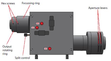
Here is a diagram showing the controls for most recent OptoSplit. Older versions may have different control names but all the controls are located in the same place.
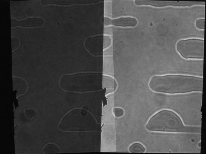
The rough edges in the image are a classic case of dirt on the aperture blades and can be remedied by cleaning with a lint free lens tissue.
This is a routine application for the Optosplit as the product has had provision for corrector lenses in one or other pathway since its inception. This facility was originally provided for correction of any chromatic aberration in the preceding optics but rapidly found a further application for deliberately defocusing one or other imaging pathway in order to allow different depths to be in focus at the same time! Obviously for z plane splitting a beam splitter is used rather than a dichroic. You may also be interested in our optosplit III which allows three different depths!
Cairn filter cubes accept standard 25mm diameter emission filters. We strongly recommend the Chroma ET range to maximize levels of light transmitted.
For dichroic beamsplitters, we recommend 26mm x 38mm x 2mm (for other sizes please get in touch with us and we will be happy to advise).
After extensive testing, we only recommend Chroma 2mm thick ‘Ultra-Flat’ dichroic mirrors for minimal image distortion across all of our image splitter range. For more technical detail, see our Chroma Filters and Beamsplitters page.
For any filter or mirror advise (not limited to image splitters), please get in touch as we are UK stockists for Chroma – we are happy to help!
The simple answer is yes! Please let us know which two channels you wish to image and we can supply Cairn filter cube(s) fully fitted and QC’d with your filters and dichroic mirror.
An empty mirror cube can also be provided with instructions for fitting your own filters if they are already present in the lab.
Both models are designed for two-channel image splitting on a single camera, but the Bypass model has a simple lever to switch between split mode and single channel operation. By introducing a bypass mirror into the pathway, none of the splitter controls are moved so there is no need to realign when you return to split mode. In addition, we use longer focal length lenses for improved image quality and use magnetically held cubes for improved registration
The Cairn OptoScan Monochromator has both an entrance and an exit slit, each having an independently settable width. The exit slit width, defines the bandwidth ONLY ASSUMING that the light passed into the monochromator is a beam of zero size. This has a maximum of 30 nm.
In the real world the input light beam however has a nonzero size, and its width is limited by the entrance slit width. The maximum entrance slit width allows any ray of the passband’s center wavelength, within the accepted input beam, to pass the maximum exit slit width, with the rays at the extrema of the entrance width just barely getting through. That is, the maximum entrance slit width is matched to the maximum exit slit width. Since the exit slit width allows a 30 nm spread of the central ray described in the previous paragraph, the maximum entrance slit width is also given as 30 nm.
Fig. 1 shows the family of passband shapes for the case of one slit width set at 30 nm and the other set for sequentially reduced bandwidths. The dotted vertical lines show the Full Width Half Maximum, in all cases 30 nm, although the profile does change. For light-limited fluorescence imaging we have found there to be no practical benefit in setting different widths for the two slits because the improved spectral profile does not fully compensate for the reduction in intensity at the centre wavelength. If the application is not light limited then there could be an argument for having a smaller input slit so that the bandpass characteristics are tighter.
In software, the OptoScan user must set the center wavelength and the entrance and exit slit widths, or use a “bandwidth” parameter to set the two simultaneously. Where this option is available we would recommend it.
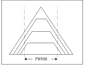
Fig. 1
The OptoScan is optimised for narrow bandwidths, so we recommend lamps with a high point intensity. We offer two 75W lamps, one an ultra-stable ultra-bright long-life lamp (1500 hours) from Ushio and another less expensive option (400 hours) from Osram – both these lamps have a high point intensity and hence are a good choice for monochromators. We recommend to always have one new lamp in the lab as a backup, as well as the one in use. They are normally held in stock and available from our sales team.
Please follow the following procedure:
(1) Check that the bulb is well within its rated lifespan. The published figures are guidelines only so although a 400 hour lamp will usually last 500 – 600 hours, if a bulb does fail at 300 hours it probably just needs replacing.
(2) Disconnect the power cable from between the lamphouse and the power supply. Inspect the cable throughly at both ends and if any of the pins have become unseated then push them back and ensure that the cable is free from stress when replaced.
(3) Taking care to wear protective eyewear remove the bulb from the lamphouse following the instructions supplied with the system (copy available on this website). Clean the insides of both electrode holders with some fine sandpaper (even a small amount of corrosion can cause striking problems).
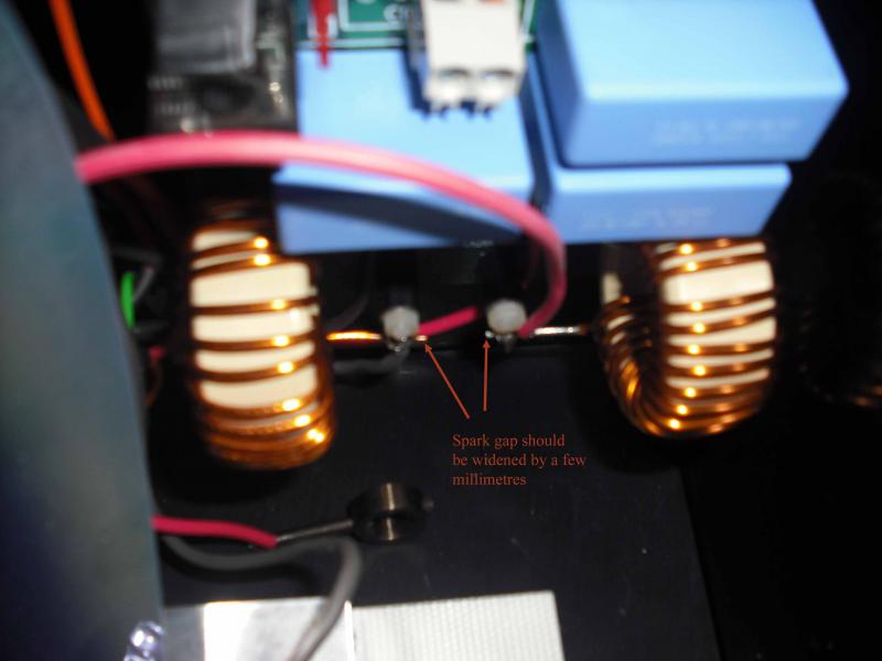
(4) If the steps above don’t work then either contact us to arrange for a return or if you would prefer to try to avoid this then it is worth widening the spark gap between the coils by a few mm. This gap provides an alternative route for the high voltage to bridge in the event of a failed bulb. Over time the impedance across the bulb can increase and the required size of the gap needs to increase slightly to ensure that the path of least resistance is still across the electrodes in the bulb and not the safety spark gap. To widen the gap either snip the end off one of the wires or bend it slightly to increase the gap between the tips.
This does sound like a faulty power supply. Please contact us to arrange to have it returned and checked out. Please do not discard the “faulty” bulbs as they may well function correctly when the power supply has been repaired. Brand new lamps are easier to strike so if the fault is marginal then it can appear to be an issue with the bulbs.
Head to the support video here for lamp changing instructions.