ALAS, POOR PLYMOUTH, BUT PARIS CONTINUES!
Martin our founder is released into an unsuspecting world after over two years of confinement, and is keen to tell everyone all about his and Andrew Hill’s LED exploits!
FREE AGAIN!
Yes, slowly but surely the world of virtual meetings is becoming supplanted by reality once again, which once more means seeing real people at real destinations, as Martin is currently doing in Paris. He is once again at the Paris Neuro workshop, for which the last real meeting took place in the spring of 2019, although it did make a virtual appearance in 2021. But it’s great to be back in the real world once again this year! In fact, thanks to that nasty little virus, this is Martin’s first visit away from his home on our nice farm for any reason since January 2020. He’s been happy to wait until there has been some sort of return to normality, which in Paris there now certainly has been. No doubt helped by good weather, the street cafes here have been doing a roaring trade during his visit, and only the requirement to wear masks on the Metro has served as a reminder of what everyone has been through since his 2019 visit.

Pretty much back to normal we now may well be, but nevertheless some things just aren’t going to be quite the same. For the world as a whole, inevitably there have been changes, but for Cairn, and more especially for our scientific interests and activities, a particularly sad event was the loss of David Ogden at the end of last year. David was very instrumental in the establishment of the Paris workshop in 2009, and was also for many years the mainstay of the Plymouth Cell Physiology workshops, which had run every year since their inception in 1984 until they too were struck down by the dreaded Covid in 2020.
ALAS, POOR PLYMOUTH! WE KNEW YOU WELL.
Unfortunately as we are all now realising, the Plymouth Cell Physiology course was very heavily dependent on David’s organisational skills (in his own words, the trick was to make sure the teachers had a good time, which we at Cairn most certainly did, as you can read here for example. But the increasing problem was that the interests of that Plymouth laboratory had long since diversified from those of Hodgkin, Huxley and others during the 1940s and 1950s in particular, where they elucidated the basic processes of nerve cell conduction, and which was the reason for basing the course there. That pioneering work took place at Plymouth because it was carried out on squid, which had some unusually large nerve cells, and for which there was a good local supply. However, technical improvements since those days have opened up a far wider range of systems to study, for which Plymouth no longer had such geographical advantages, so the course increasingly relied on teachers descending on it from elsewhere each year. And those years have been adding up! It’s now nearly 40 years since the course first ran, whereas that first year in 1984 was “only” about 30 years after the main era of the research that we’d been commemorating by holding the course there. So David’s enthusiasm for and dedication to the course had become progressively more important over the years, but it was sufficiently infectious for many of us to join him there each year.
Just like Paris, this course also “ran” virtually in 2021, but in view of its inherently practical nature it really wasn’t the same, and it was further complicated by some crazy difficulties with the lab’s IT department concerning access to the course website. And for this year, as well as our all trying to cope with the loss of David, the Plymouth laboratory space is due for extensive refurbishment, which could well have made its hosting the course there impossible this time anyway. As for next and future years, who knows? Sadly, it has become clear that Plymouth’s administration are no longer as supportive of this type of activity as they once were, and my sources tell me that has already resulted in the ending of the optical course that used to take place there every spring (and in which Cairn had also regularly been involved), so the future of the Cell Physiology course is correspondingly more uncertain. Something may well happen somewhere in future years, but whatever that may be, David’s passing has certainly marked the end of an era that has been particularly important to and enjoyable for Cairn. I’d been delighted to participate every year since I went full time with Cairn in 1989, and with at least one other Cairn person coming with me since 1993, it had a correspondingly special place in our calendar, for which no other activity can possibly substitute.
BUT PARIS CONTINUES!
But to coin a phrase, it looks as if “We’ll always have Paris” , for which the continuation has been much easier as so many of the teachers are based in this fair city, as David himself had been for a number of years, and where his enthusiasm had again proved infectious, so let’s now turn our attention here! I’m here to give my usual talk on light sources, and Cairn’s CEO Jez Graham will be here shortly to talk about cameras. However, this time I do have a slight “problem” in that in my talk I deliberately give a general discussion of the physics and the technology rather than attempting to promote Cairn’s admittedly fantastic products in any sort of commercial way, but it does just happen that this meeting is the first time that my and Andrew Hill’s latest technical endeavours have reached the light of day – or more precisely, of LEDs! But although I couldn’t make my presentation too overtly commercial, I am under no such “restrictions” here, hence here goes!
So what have we been doing with LEDs exactly? Actually the answer is quite a lot! Some of this took place under the cover of “lockdown”, but that also interfered with us telling the world about it before now, so there is much catching up to do here. Also to be honest, the whole story has only just been emerging, as several individual projects have come to fruition together, and are literally being demonstrated here for the first time. In fact it has even felt as if they were part of some overall strategy. This is of course because there actually was one, but at least from my perspective it seemed more like several different applications of straightforward common sense, so it was particularly nice to see them finally combine in the way that they now have. So please let me explain a little further…..
LEDS – THE PROBLEM IS YELLOW AND OUR ANSWER IS FOUR! BUT FIRST, THE PROBLEM
Compared with the technical issues of designing xenon light sources, and which because of the “yellow problem” we are likely to have a continuing demand for our now long established Optosource design, getting an LED to light up is not exactly difficult. So at Cairn we have tried to distinguish our products from the competition by offering more “advanced” features such as optical feedback and fast digital switching, and these are continuing to serve us pretty well. However, until now we have been offering systems such as the OptoLED, TwinLED , FuraLED and MacroLED that individually support just one or two wavelengths, although we have sometimes provided additional couplings to allow any of these units to be combined.
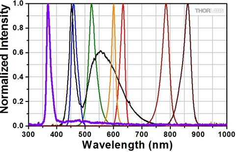
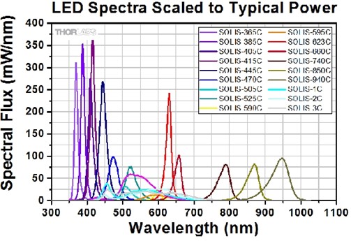
On the other hand there is a fair range of commercial LED products that directly provide multiple wavelengths, but as nice as they may be, they still do not get around the fundamental problem that some LED wavelengths are significantly brighter than others. This important difference is usually obscured by their spectral output being shown relative to the peak wavelength, which is then defined as 100%, and then comparing the spectra on this basis, as for example the first graph from Thorlabs shows. However, the second graph, also from Thorlabs, shows the real situation. That shows that LEDs can be very bright in the UV, blue, red and infrared, but in the green and especially yellow the situation isn’t nearly as good. We tend not to notice this visually, as these are the wavelengths to which our eyes are most sensitive, but it’s the number of photons, or more correctly the relative shortage of them in this region, that really matters here.
Therefore, no matter how many LED wavelengths we may wish to combine in pursuit of a broad spectrum LED source, we are still going to be stuck with this fundamental problem. And it turns out that there is a similar problem with lasers, especially with laser diodes, which tend to share the simplicity of LEDs when it comes to driving them, but again you are out of luck if you want a yellow one!. So what can be done? Well, you can “make” a yellow laser, albeit by technologies that are beyond my own expertise, but such a beast is particularly temperamental in respect of thermal stability in particular, so it requires very careful temperature control, and can’t be rapidly modulated (at least directly) in the same way that LEDs and laser diodes can. This approach is the basis of 89North’s LDI multiwavelength laser light source, and in which we are pleased to declare an interest in respect of our being a formal distributor, and it really is a very nice unit. However, the complexity involved in solving the “yellow problem” means that all this inevitably comes at a price!
SO WHY FOUR IF YOU SAY NO TO YELLOW?
Hence our approach continues to be that if you really want or need yellow, then save up for one of those nice units, but if you don’t, then forget about trying to cover the whole spectrum, in which case how many different LED wavelengths are you likely to need? This is where we came up with “four”, which makes sense in a number of practical ways if two aren’t going to be enough. It’s easy to do two, just by having two LEDs at right angles, with the light from one LED going through a “dichroic” wavelength combining mirror, and the light from the other LED being reflected by it, so that the two wavelengths are now heading in the same direction. Since they are now effectively from a single LED, you can further combine the light from two such units in the same way, by using a further combining mirror, so there are now three such mirrors in all, with the light from any one LED encountering two of them (being either transmitted or reflected) in series.
In terms of optical path lengths, this is therefore a completely symmetrical and still relatively compact system, whereas to do anything less than to double up again (which would give you eight wavelengths, but would you really need that many?) that elegant simplicity would be destroyed, plus at least one LED would now encounter three mirrors. Our new coupling system, which is modular, fully supports any such possibilities, but the latest versions of our electronics specifically include one that can independently drive up to four LEDs from a single controller box. This saves both space and money compared with the (albeit continuing) alternative of using two two-channel controllers.
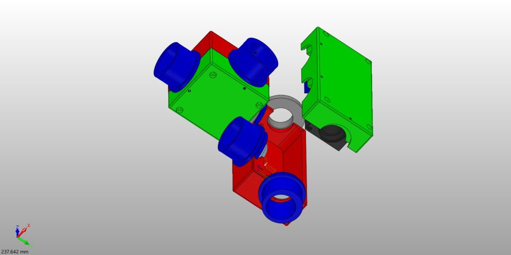
As you can see from the partially exploded diagram above, for combining four LEDs (which you insert into those cylindrical blue components) we save further space by putting two of the three mirrors in a somewhat longer box, and each box is machined from just two parts, with the (easily interchangeable!) mirrors housed in the lids. The mirrors can either be in our standard cubes, or if you don’t want or need to use filters (although they are generally a good idea), then an even simpler holder, that just takes a mirror, can be used instead. And this is all sufficiently compact that you can usually connect it to your microscope directly, thereby avoiding the expense and possible losses of using a light guide.
And now we can also offer a fully programmable four-channel USB interface, with a nicely informative alphanumeric display on the system box, as well as some very nice GUI software that our Andrew Hill developed, and which allows just about all functions to be controlled from a computer. This will deserve (and get!) a much fuller description in due course, so we only give some basic information here. But for example, the individual and readily interchangeable LED heads for each wavelength can now have built-in memory chips that tell the both the display and the interface such parameters as the wavelength of the LED and the maximum current at which it can be driven, which allows the “full scale” level of these controls to be set with respect to that maximum. We’ve also thrown in some programmable timer facilities for good measure, based on some timer routines that we had previously needed to develop for our Optospin25 & OptoSpin32 filter wheels, and which therefore required correspondingly less development time than if we’d started from scratch. Plus various other stuff that you can read a little more about here
NEW LED ALIGNMENT SYSTEM
And now your blogger is going to have a little fun! You might have thought that when he (because it was he) came up with this coupling and alignment system, there would have been much enthusiasm and excitement for it within Cairn. Er, no…. I actually came up with it pre Covid, but the response at the time was basically that we’d “got couplings” already, and my protestations that it was cheaper, more compact and was especially suitable for four-LED systems cut little ice then. So our first batch (I was confident enough to order five “prototypes” rather than just one) stayed mostly unwrapped until just a few days ago.
But meanwhile I’d been developing our USB interface, which was explicitly a four-channel version from the start, even though we had primarily envisaged it being incorporated into our various two-channel units. However, we couldn’t help but notice that the alphanumeric display that we had chosen to use with it was available in both two and four channel versions, so the obvious next step was to see if we could somehow cram four LED channels into our standard two channel box. The answer was yes but it was a tight squeeze and the wiring of the prototype was very messy, but both problems were rectified by improving the layouts and interconnections of the internal circuit boards, and the production version has now just come into being. And by this time, Andrew’s GUI (graphical user interface for control and display via a computer) was just seeing the light of day, so now we had the complete four-channel system that we’ve just been showing in Paris.
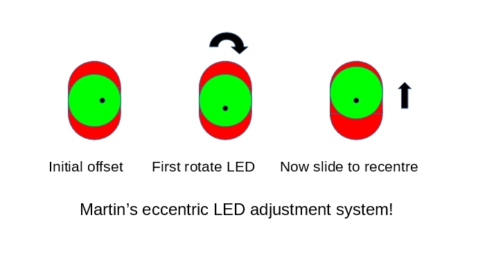
First, the adjustment is in “imaging” rather than “infinity” space, as it changes the x and y position of each LED relative to the lens that collimates the light from it. The optical rule here is that a positional change in “imaging” space changes the beam angle in “infinity” space, so it’s equivalent to changing the angle of a mirror, but with the advantage that the adjustment is now specific to each individual LED, whereas the mirrors may be shared. Second, the adjustment is apparently in one direction only, because it’s based on the LED holder being able to slide up and down relative to the coupling box and hence the LED’s collimating lens, which is mechanically very simple to arrange. But how do we do the “other” direction? Easy! The trick is to make the hole in the coupling that takes the LED somewhat off centre with respect to this sliding action (look at the shape of the blue components!), and to allow the coupling to rotate relative to the box.
Let us assume that we need to make the adjustment because the LED isn’t fully centred in its housing, although the principle is the same for whatever other reason that we may wish to do so, e.g. if a mirror reflection angle isn’t exactly correct, in which case we are deliberately offsetting the LED to compensate. But either way, we are going to be adjusting so as to centre the beam onto the rear aperture of the objective, which is of course what actually matters. So let’s assume that the beam position at the objective is as if the LED is centred at some distance from the geometric centre but displaced in say the 3 o’clock direction. We can only move the LED and its holder “up and down”, but we can also rotate the LED and its holder together. Since the LED is offset from its holder, this has the effect of changing the displacement angle, so we just need to rotate so that the angle is now at 12 o’clock or 6 o’clock instead. We can now centre the (effective) position of the LED by sliding the LED and its holder up and down with respect to the collimating lens. All done with just this one component! Oh, and it controls the focussing too, which just involves sliding the LED in and out.
Compared with a conventional x and y type of adjustment, this may sound rather less convenient, but in practice at least we don’t find it so. We think this is because although dedicated x and y controls might sound easier to use, in practice it may not be be so immediately obvious which direction is which with respect to the beam position at the objective! Another advantage is that although the adjustments are effectively external to the box, the couplings aren’t any bigger than they would be for a fixed design, whereas since the mirrors can now be fixed, we don’t need to provide any additional internal space for adjustment mechanisms for them. The result of all this is that the whole system is much more compact than you might expect, so it can quite easily be attached directly to a microscope, with the consequent cost and efficiency advantages of not needing to use a light guide.
But now and finally, back to our new coupling and LED alignment system! For microscopy use, it’s particularly important that the LEDs are aligned as accurately as possible, as they normally need to be focussed into the back of a microscope objective through a relatively long optical pathway. Where an optical pathway includes a reflection in an “infinity space”, as is the case for the mirrors in any coupling system of the type just described, then you can steer the reflected beam around in the x and y directions by making small changes to the mirror angle. However, where the mirror is internal (as it usually is!), then that isn’t so convenient, whereas some at least small adjustment is likely to be necessary whenever you change an LED – and that’s something that we want to make easy to do. But worse, unless you specifically include an extra mirror for the purpose, then even in a four-channel coupling there will be one LED pathway that won’t have been reflected at all, and so cannot be aligned in this way.
So we have come up with an alternative solution, and which turns out to work even better than we had hoped. It’s ludicrously simple, as it’s based on just ONE component (the blue one in he previous diagram), whereas even adjusting a mirror angle tends to require some sort of “mechanism” in order to achieve the independent movements in x and y. With this alternative solution, we can leave the mirror angles all fixed, and instead apply the method directly to each LED, and for which it is directly accessible because the adjustment is an external one. But it does perhaps require a little explanation, which we hope this diagram will make clear.
I’m pleased to say it’s been getting some rave reviews here! It really does look as if we have come up with something rather nice. And to be fair to our local crowd (much as I hate to do so of course), when they saw the coupling system used in conjunction with the four channel box with its USB interface, they too were perhaps beginning to see the point of it. Which I hope all goes to show that although the Company is now owned by our employees rather than by me, I still intend to be useful!