A Book that Should be on Every Experimental Scientist’s Shelves
Martin reviews Basic Statistics for Life Sciences, explaining why stronger statistical understanding is vital for experimental biological researchers.
Martin reviews Basic Statistics for Life Sciences, explaining why stronger statistical understanding is vital for experimental biological researchers.

A Sudden Shift in Seasons at the Cairn Farm Goodness, the season at the Cairn farm has suddenly changed in the last few days!

Harvest time at Cairn Research! See what’s happening on the farm and get the latest on our MultiScope project and upcoming microscopy innovations.
We are delighted to announce our new partnership as an official UK distributor of Argolight calibration slides.
We are excited to announce a new collaboration with Dr Alex Corbett, Senior Lecturer at the University of Exeter, and Royal Society Fellow.

A quick look at seasonal changes on the farm, with cherry blossoms in full bloom, the transition from old orchard trees to new growth, and a touch of charm

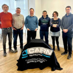
We’re excited to announce that Linda Hall has returned to Cairn Research as our Operations Manager! Here’s to continued success.

Cairn Research celebrates 40 years of innovation in scientific instrumentation. A journey of growth, discovery & commitment to microscopy & optical solutions.